(日本語) 今年1年のそふらぼ教授部屋
ヤモリ教授omznです.
ことしのomzn周辺で起こった話をつらつらと.
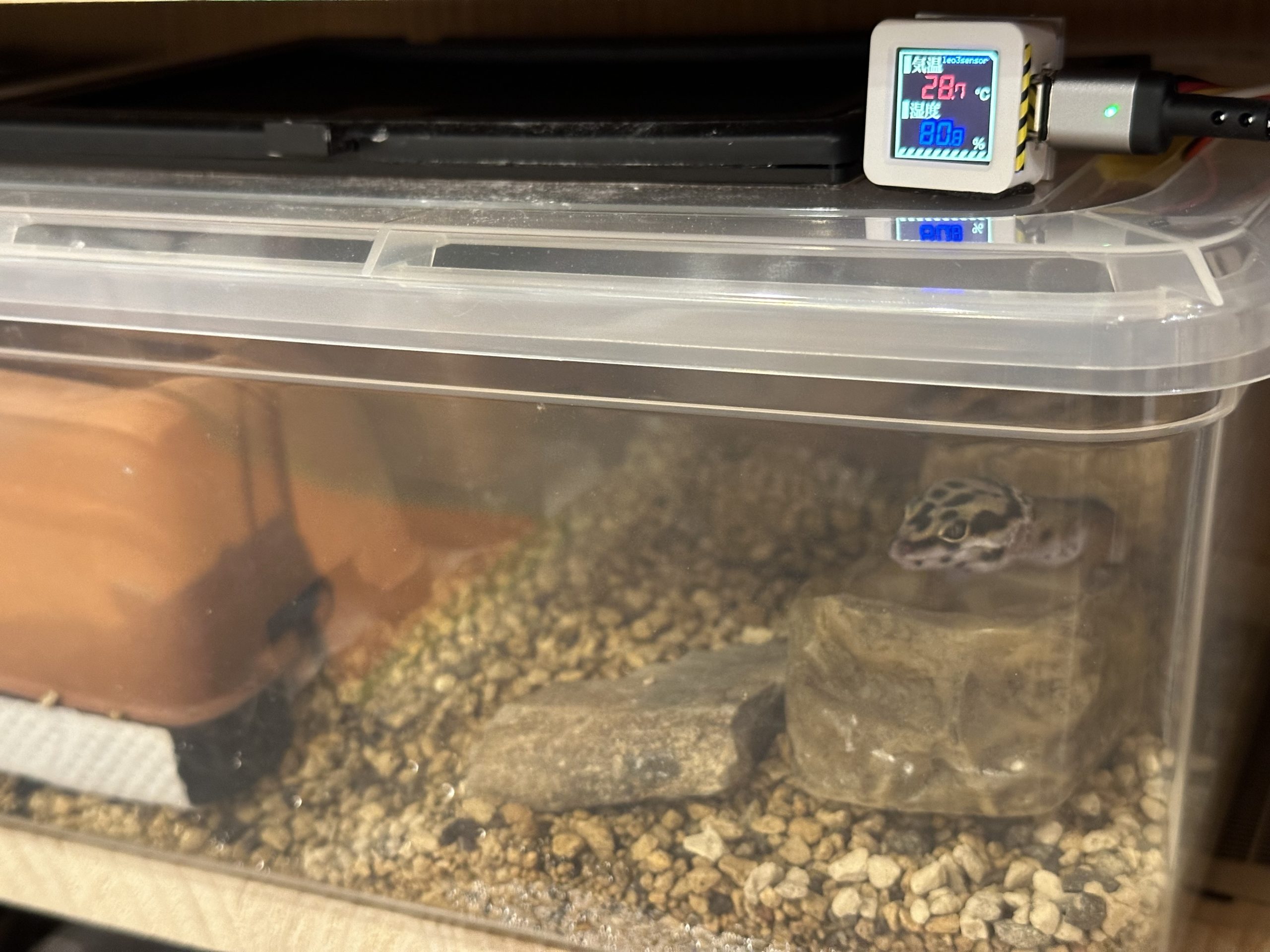
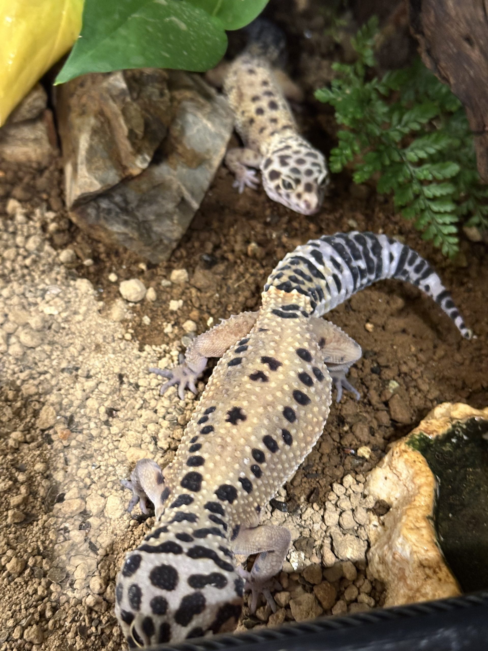
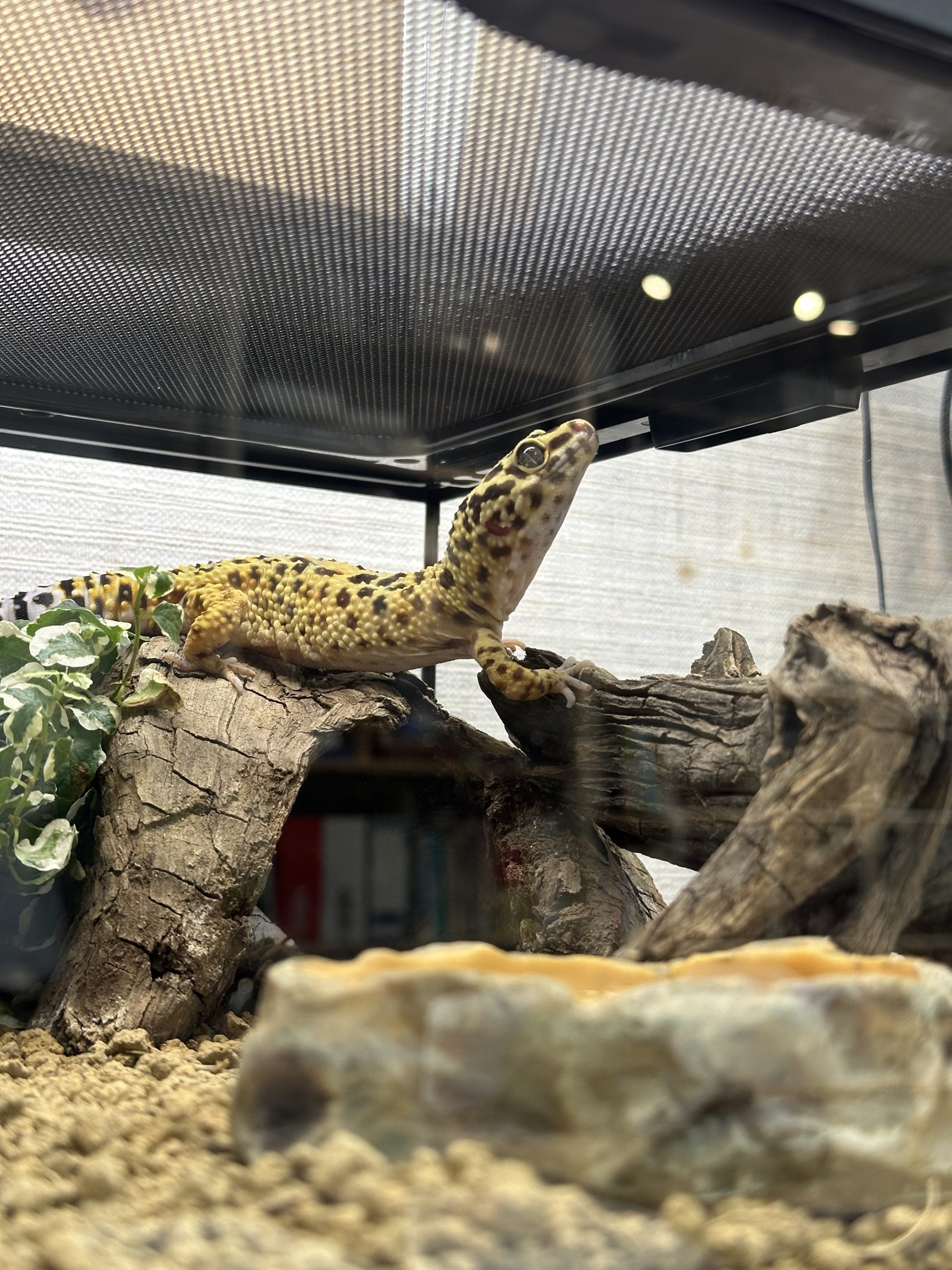
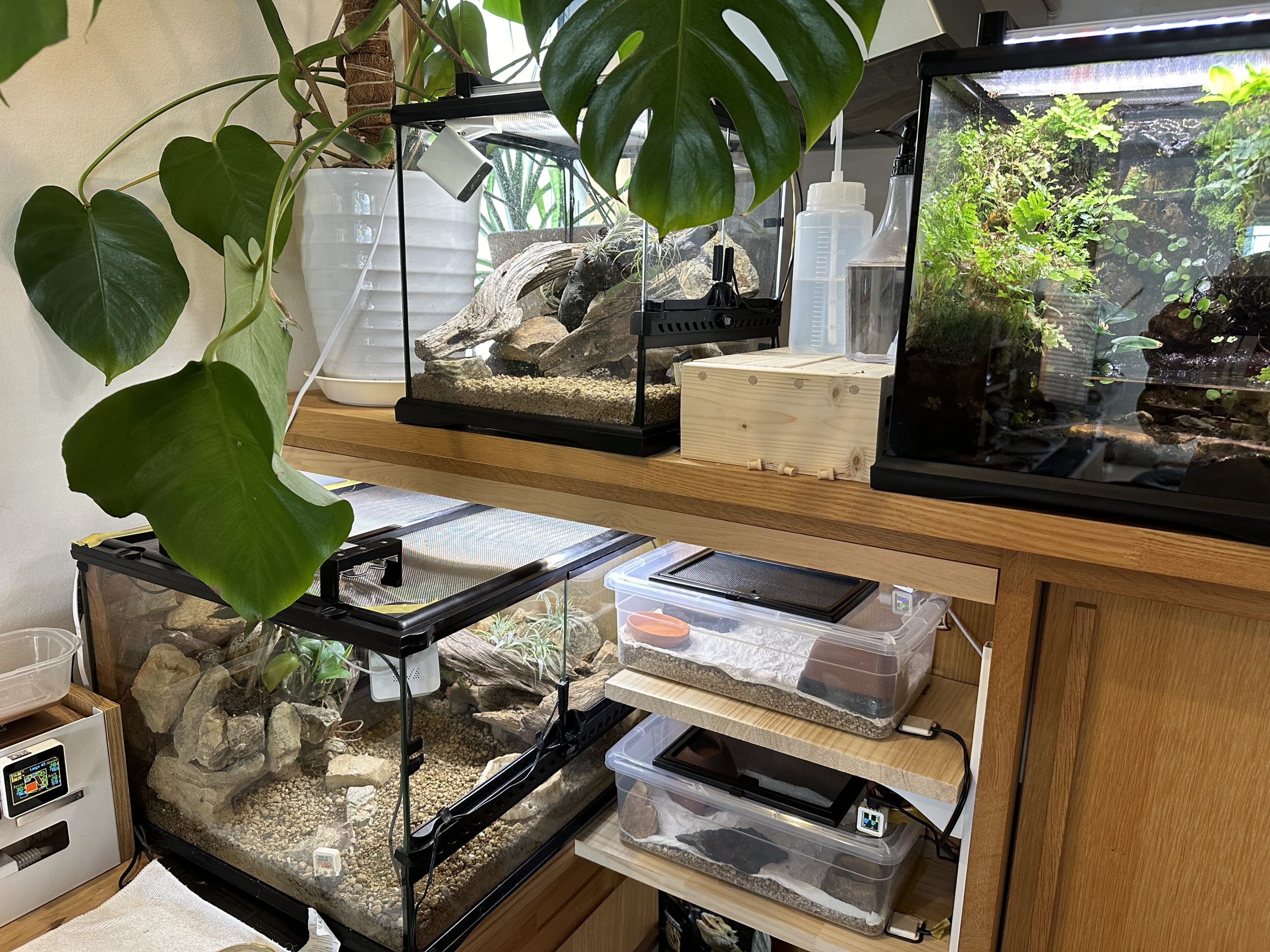
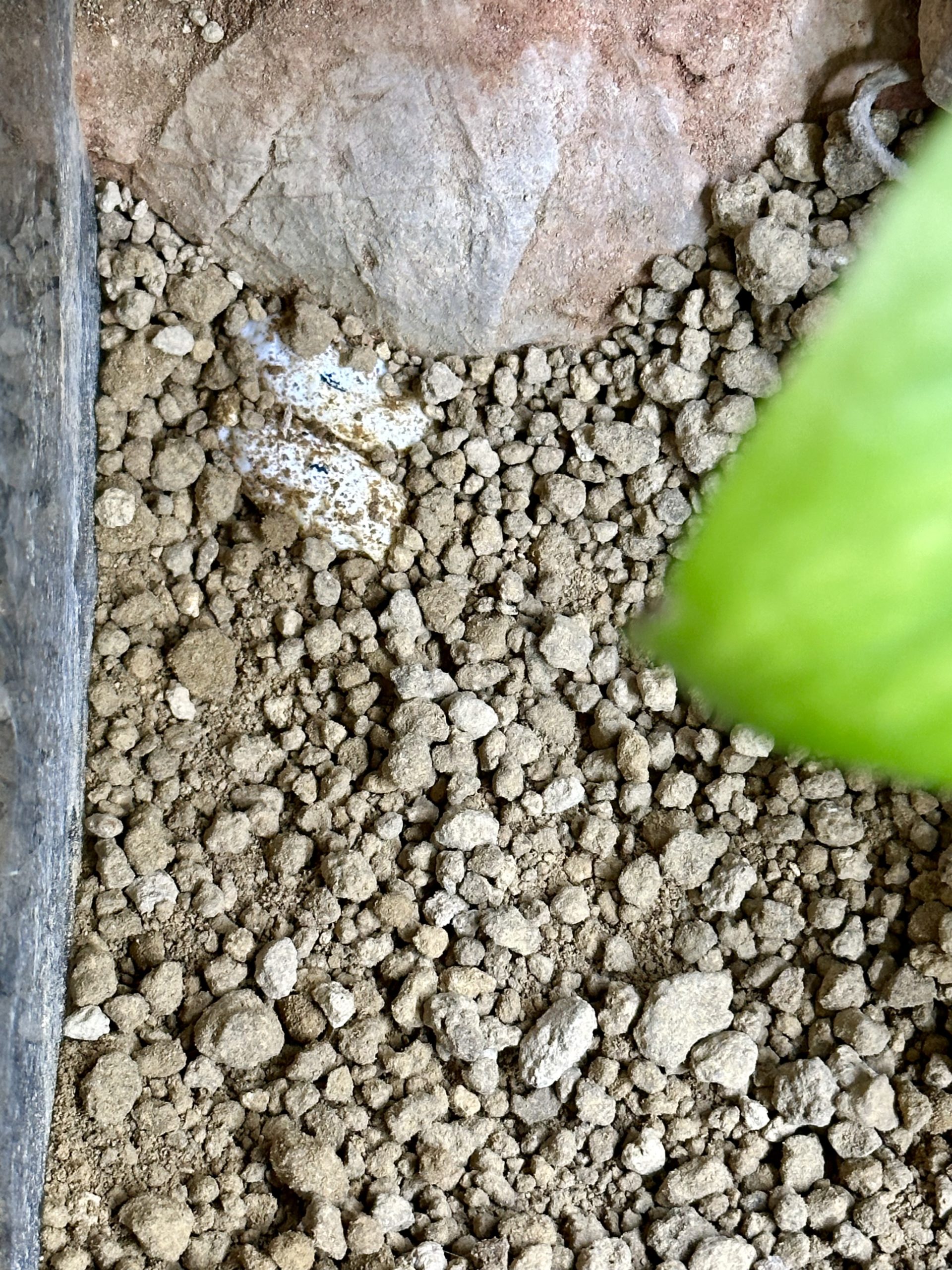
今年のレオパケージ
昨年生まれた3匹がどんどん成長していきました.
- Groot → 95g
- Good → 54g
- Star → 50g
親世代もだいたい50g前後なので,そのあたりが標準体重なのでしょうが,Grootだけ突出してでかいです.
一応,レオパには「ジャイアント」という品種があって,90〜120gになるらしいのですが,こいつだけジャイアントの遺伝子が発現してるのかなと思うぐらいでかい...エサも他の子の2倍ぐらい食べます.
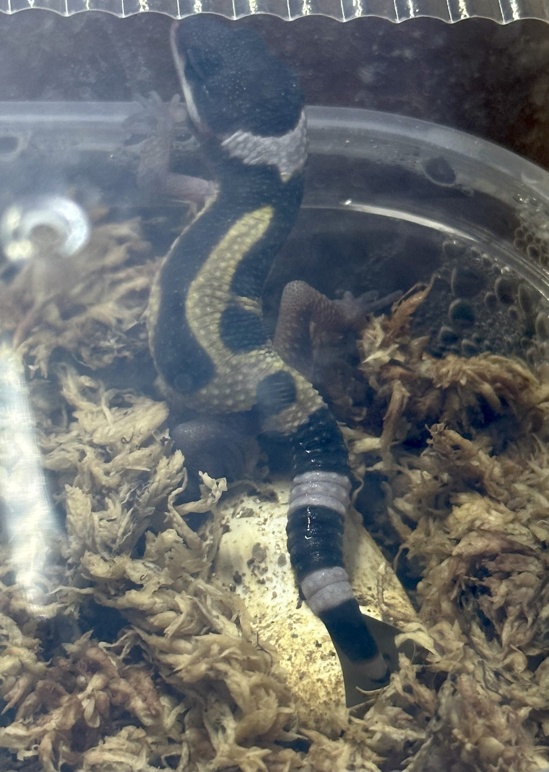
なお,全員メスだと思い込んで同居させていたのですが,Starはオスだったことが発覚しました.
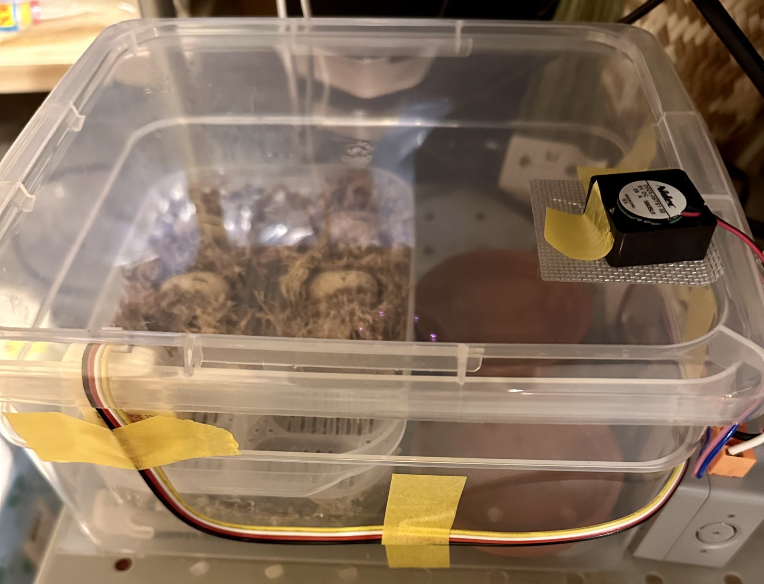
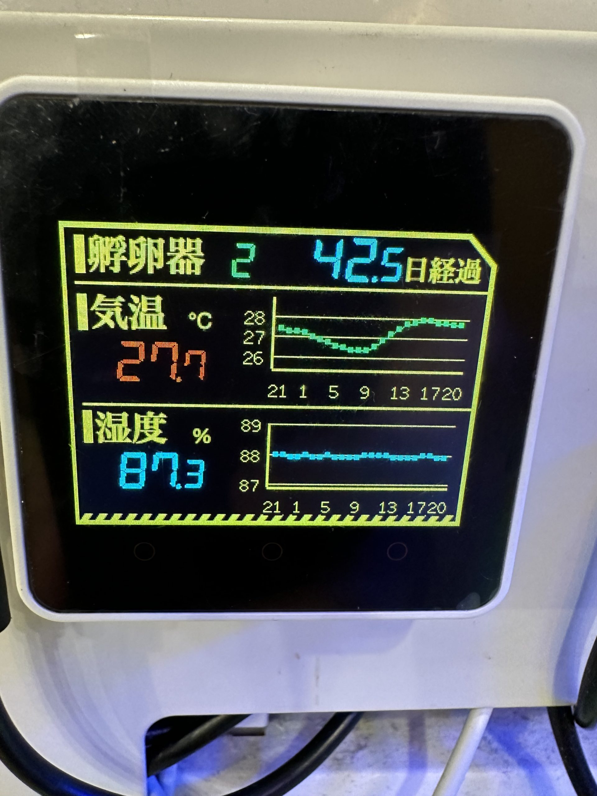
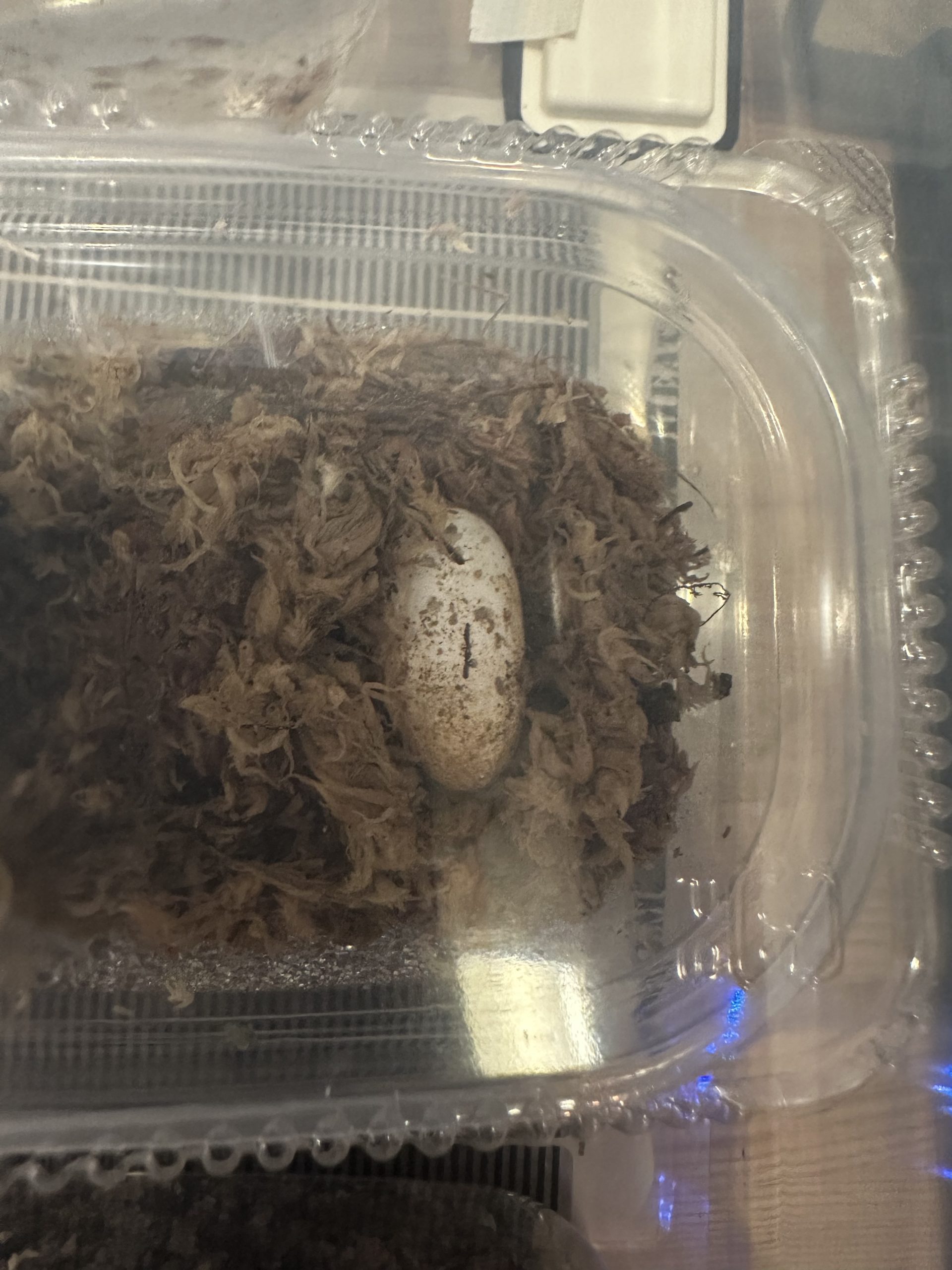
気づいたときには,Goodのお腹が大きくなってきてしまい,現在,絶賛孵卵中です.
Star君は単独で隔離され,そのあおりで,親世代のVee君がそふらぼに連れてこられる羽目になりました.
現在,自宅に3ケージ,らぼに1ケージの4ケージ態勢です.
エサ
今年から,今まで手を出さなかったエサ,「デュビア」にチャレンジしています.
デュビアってのは学名の一部なんですが,和名は「アルゼンチンモリゴキブリ」です.
環境に漏出すると大変な感が漂いますね.
しかし,フタホシコオロギに比べて利点が多いのです.
- 草食性なので臭くない
- 共食いしない
- 鳴かない
- 耐久性が強い
- 育ちが遅い
怖い点としては以下.
- Gである
- 成虫は5cm越えに成長し,圧が強い
繁殖も簡単っぽいので,何匹か成虫を残して育ててみようと思っています.
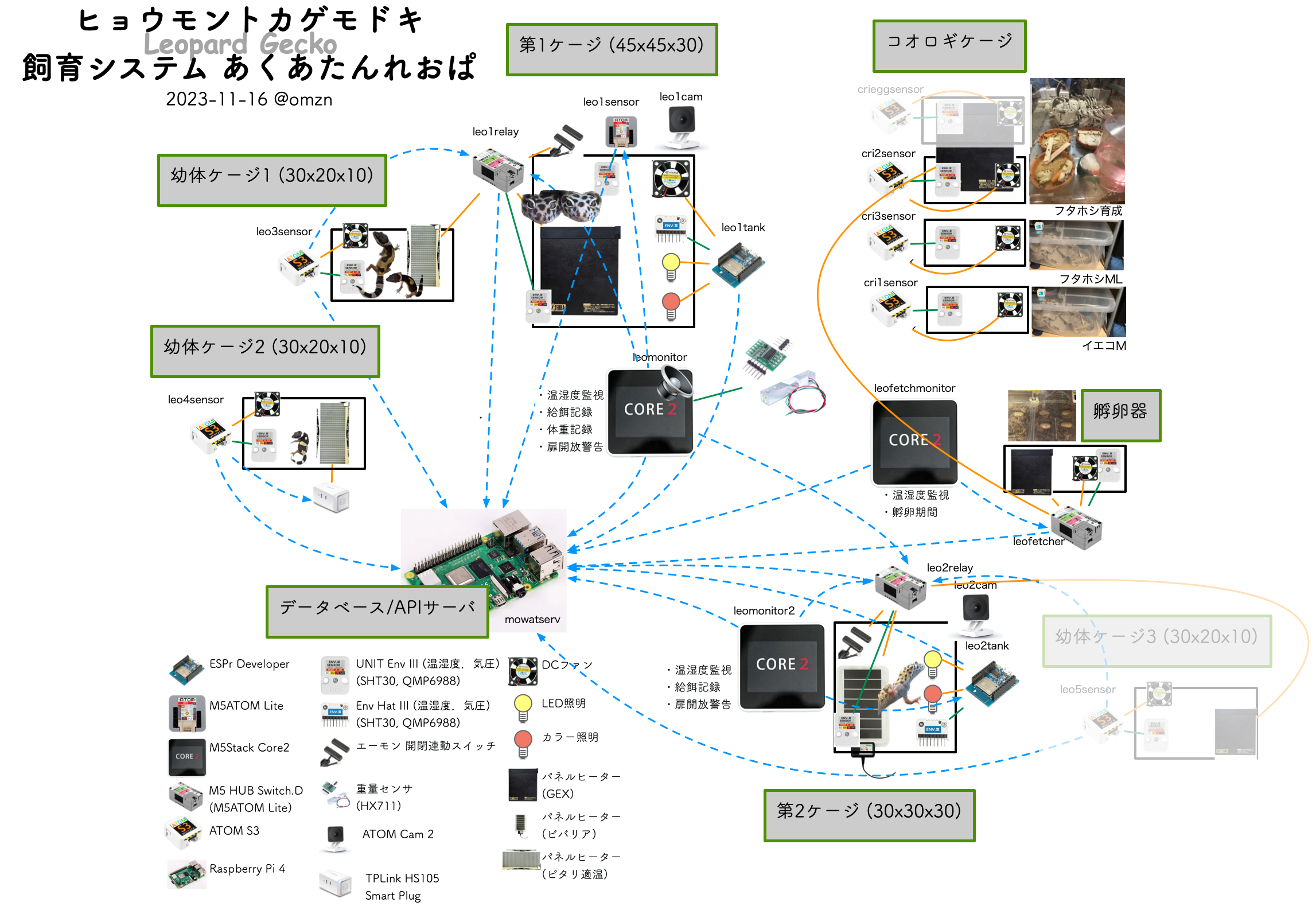
あくあたん
あくあたん水槽システムにとっては,今年は激動の年になりました.
部屋の改修に伴って,これまでの水槽を全て撤去し,全く新しく水槽を1つ作ってやることに.
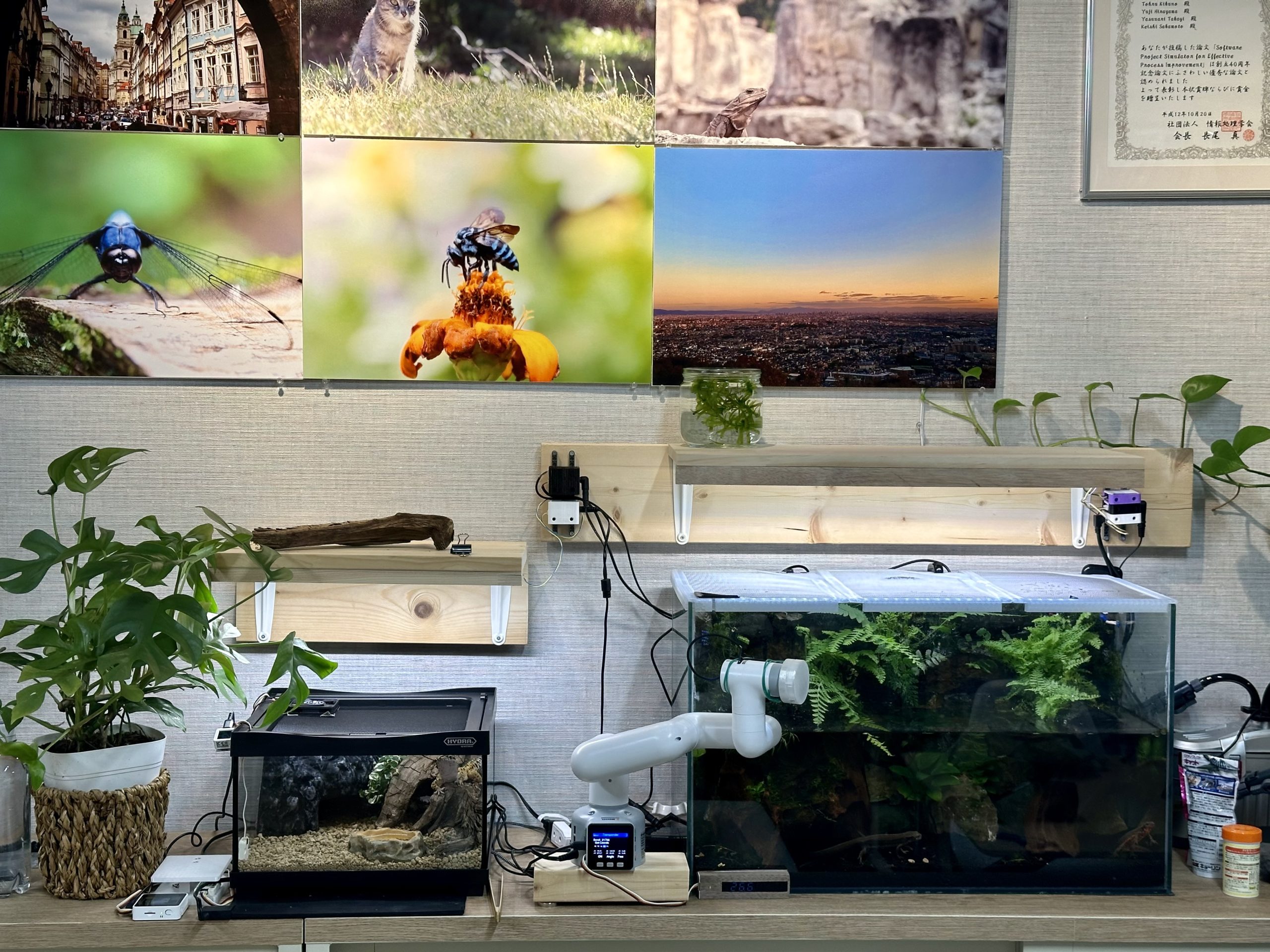
新水槽には霧発生装置から定期的に霧が出ます.
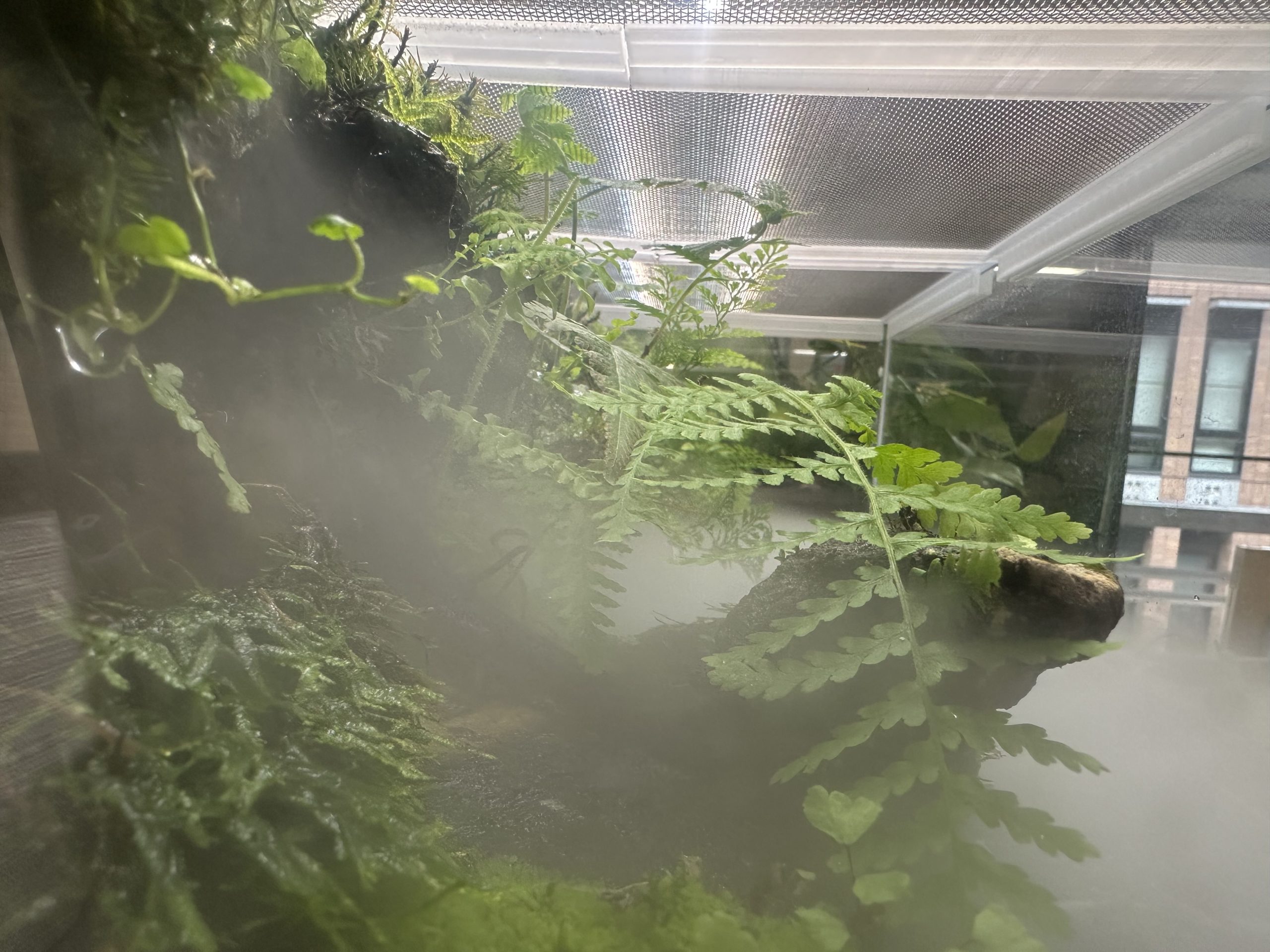
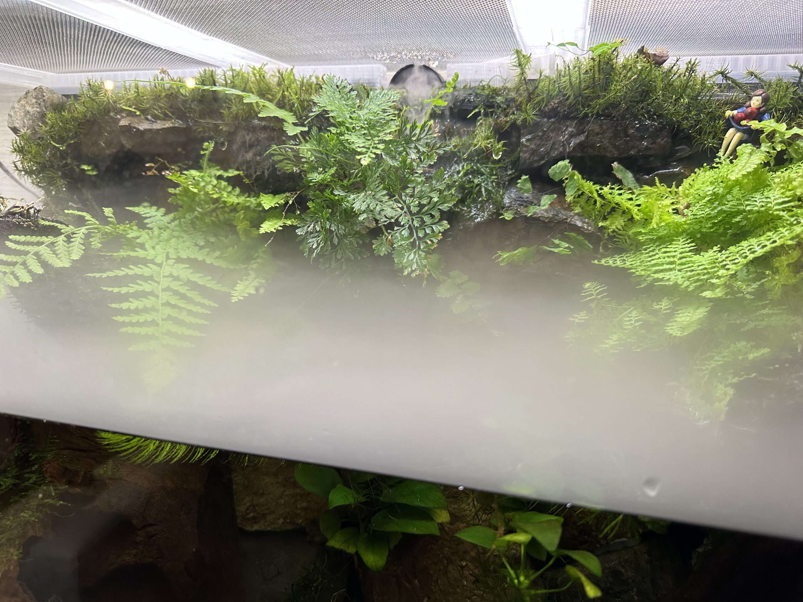
カメラ移動はロボットアームに任せることになり,謎感とレゴ感が減ったのはちょっと悲しいです.
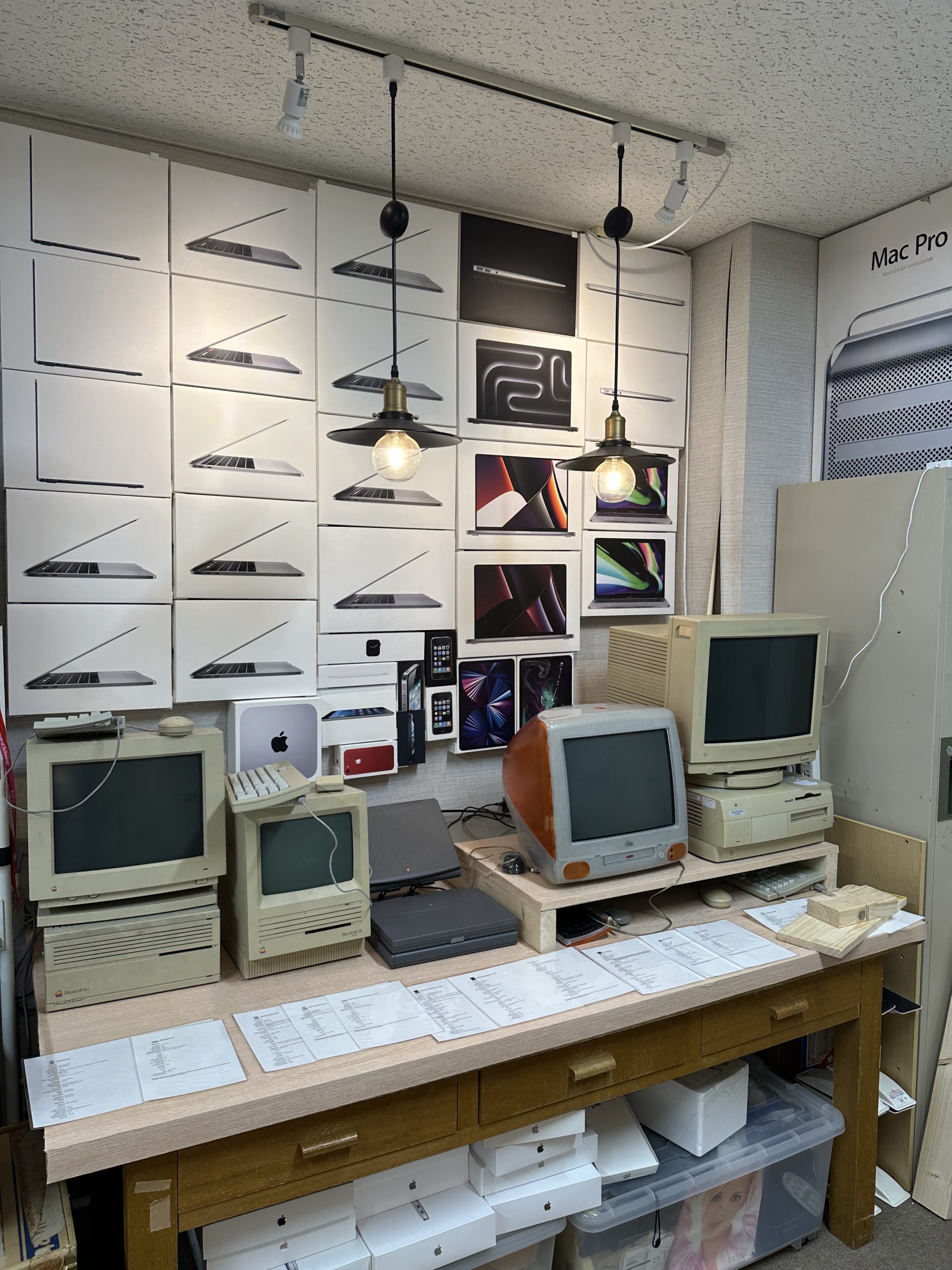
Mac博物館
念願のMac博物館も開設しました.みんな可動実機です.
まとめ
時間が無かったので,今年はこれぐらいで.
みなさんHappy Merry Holidays and Happy New Year!
")


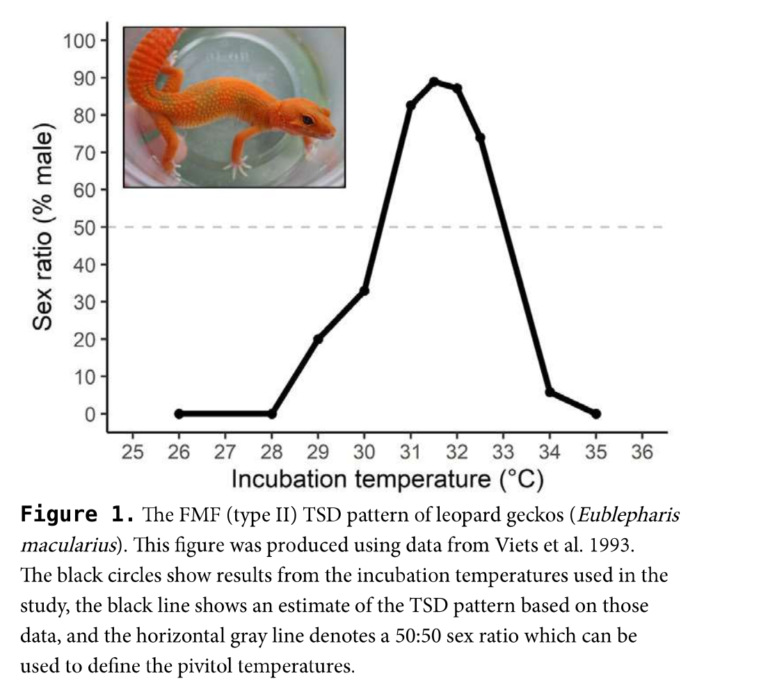 ヒョウモントカゲモドキの温度依存性決定([1]より引用)