This article is the 22nd day of the advent calendar of Studio Aquatan 2023.
Hi, this is Prof. omzn (keyboard modification studies).
This is a continuation from a week ago.
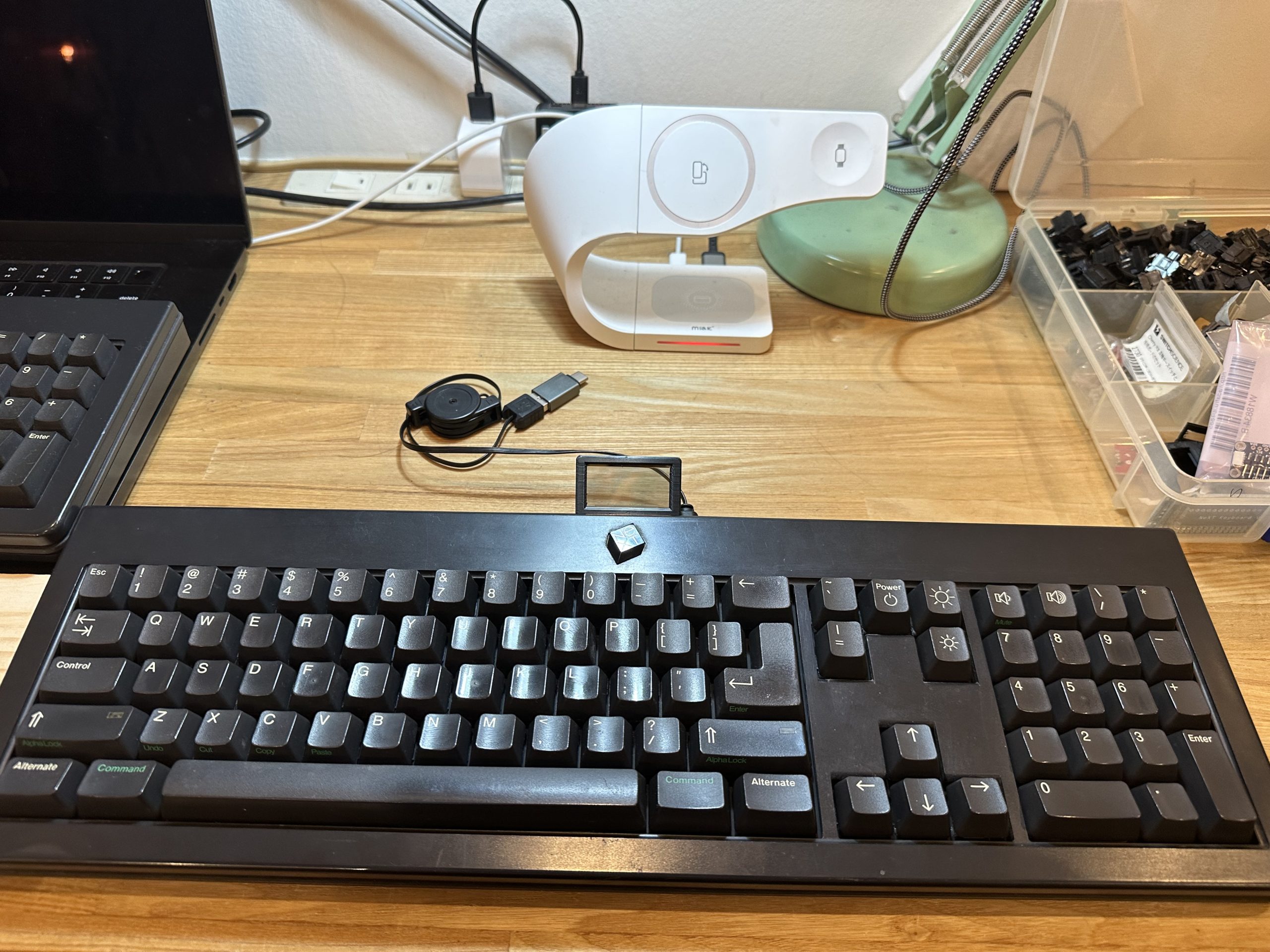
Reiwa NeXT keyboard V2
Actually, I have an unmodified NeXT keyboard, but this one is junk and does not work even if it works.
I decided to modify this one, too.
The eBay price of the NeXT keyboard as of December 2023 is as shown below.
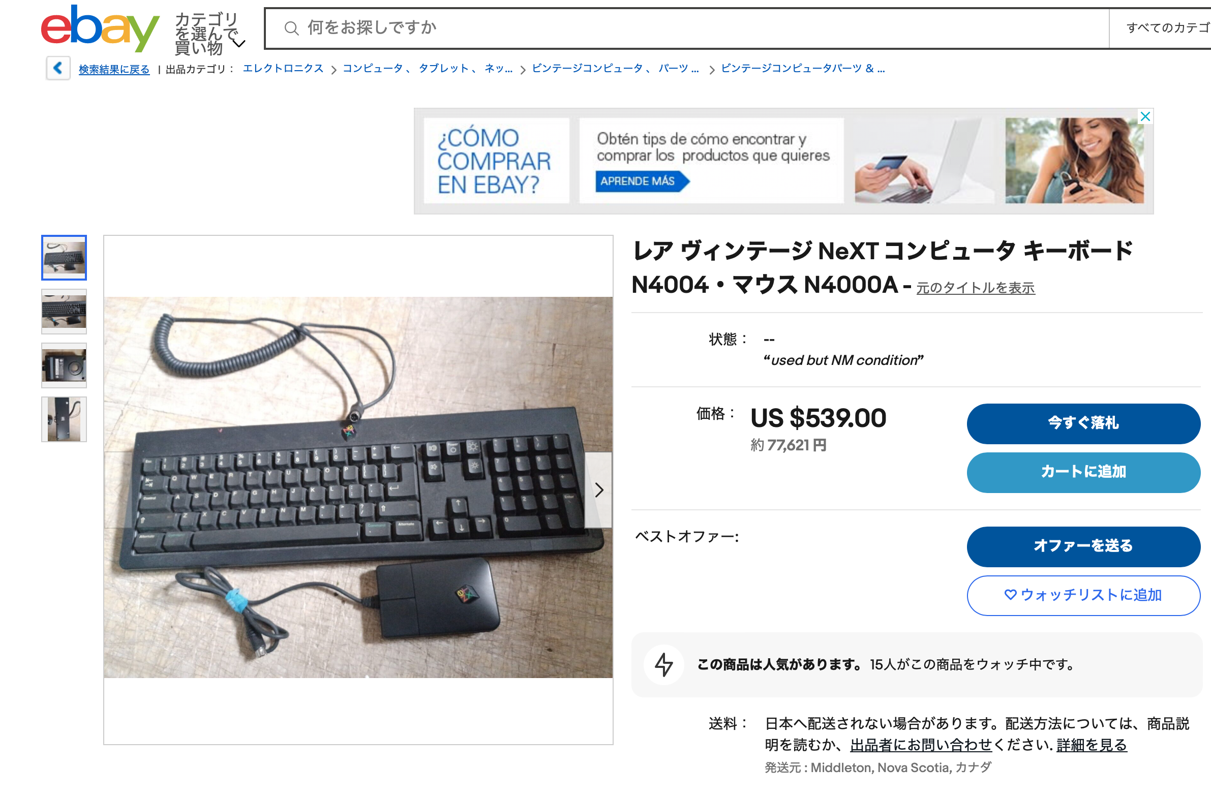
I’m so nervous about wasting it…
Now, we will realize the following three points.
- No pattern cutting
- Change the physical keys to compatible ones
- Make them light up
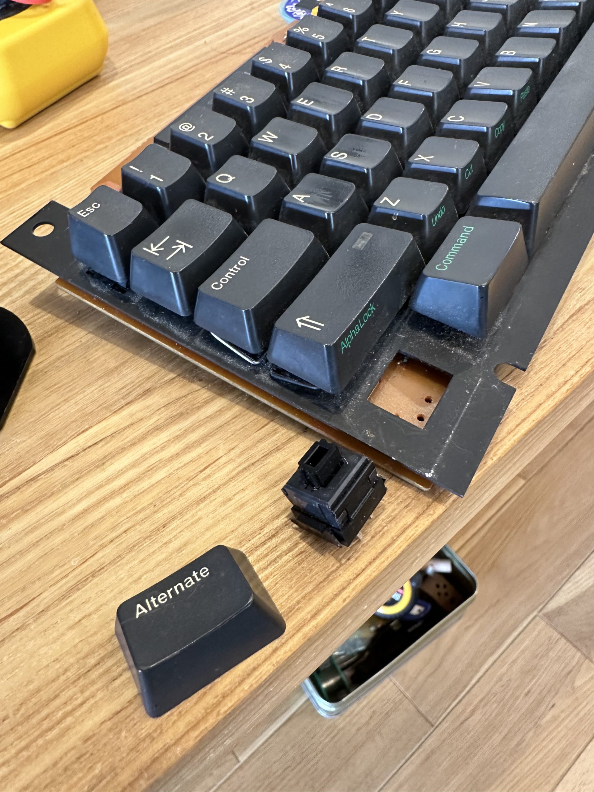
Key layout
Similar to V1, but the Return key is inverted L-shaped, and the backslash key is pushed out to the numeric keypad.
The backslash key is pushed out to the numeric keypad.
The engraving looks like old Macintosh.

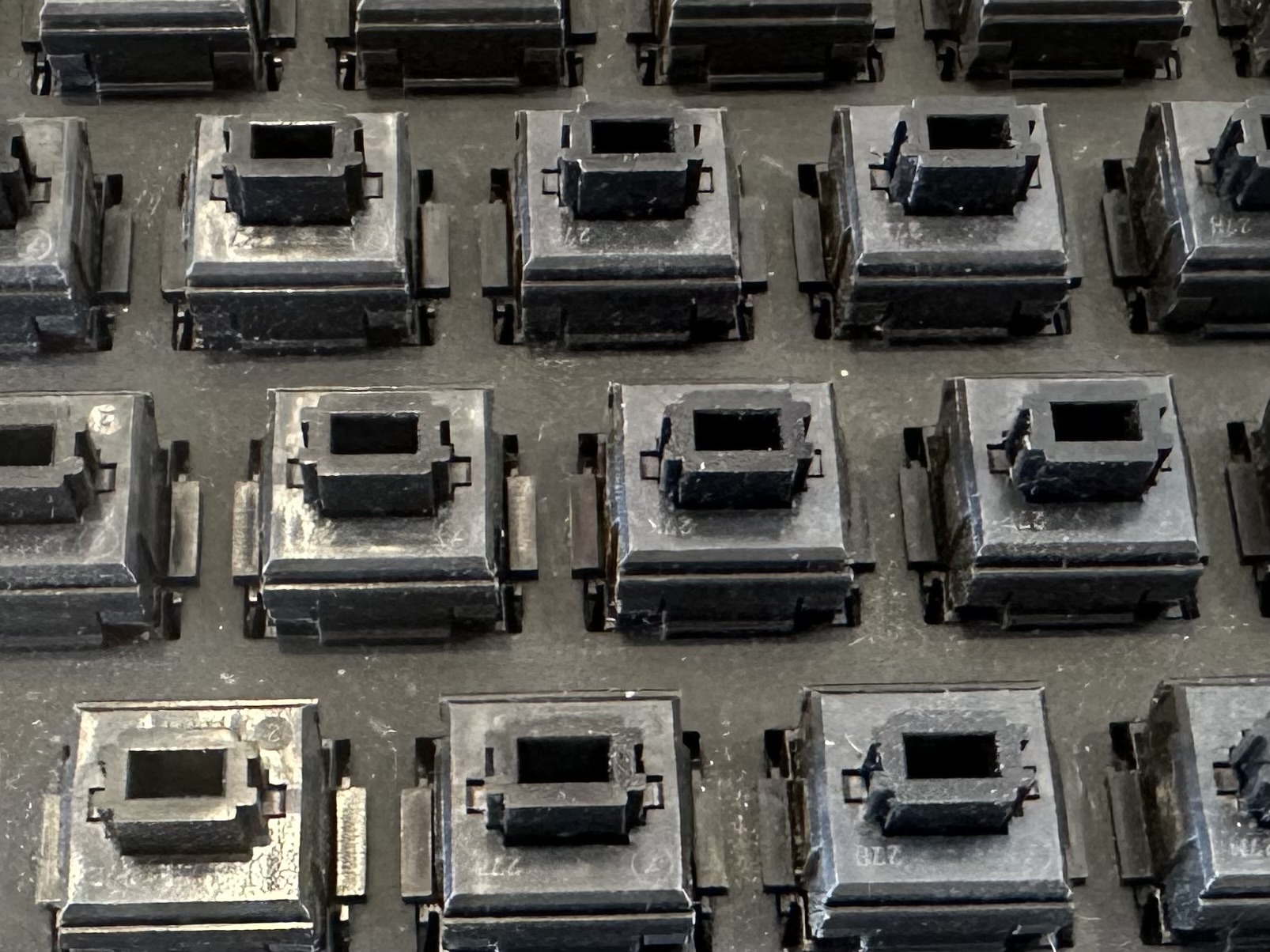
Physical keys
This keyboard uses ALPS black keys.
The ALPS axis is no longer manufactured by ALPS Electric.
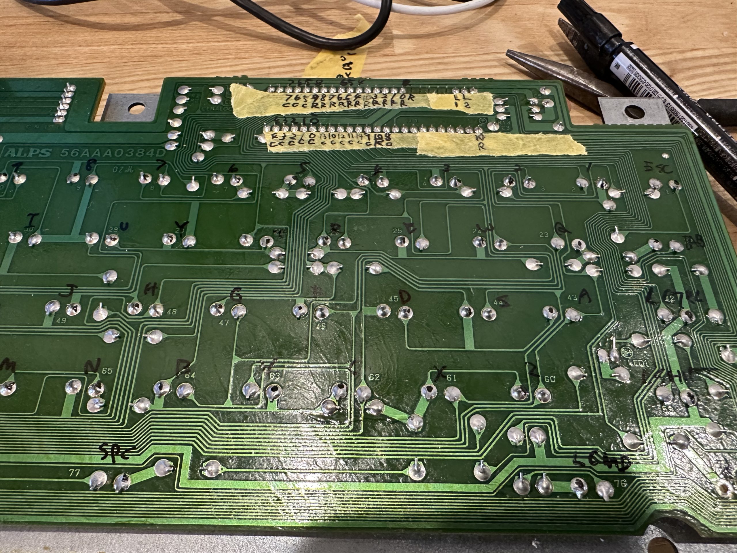
Key Matrix Analysis
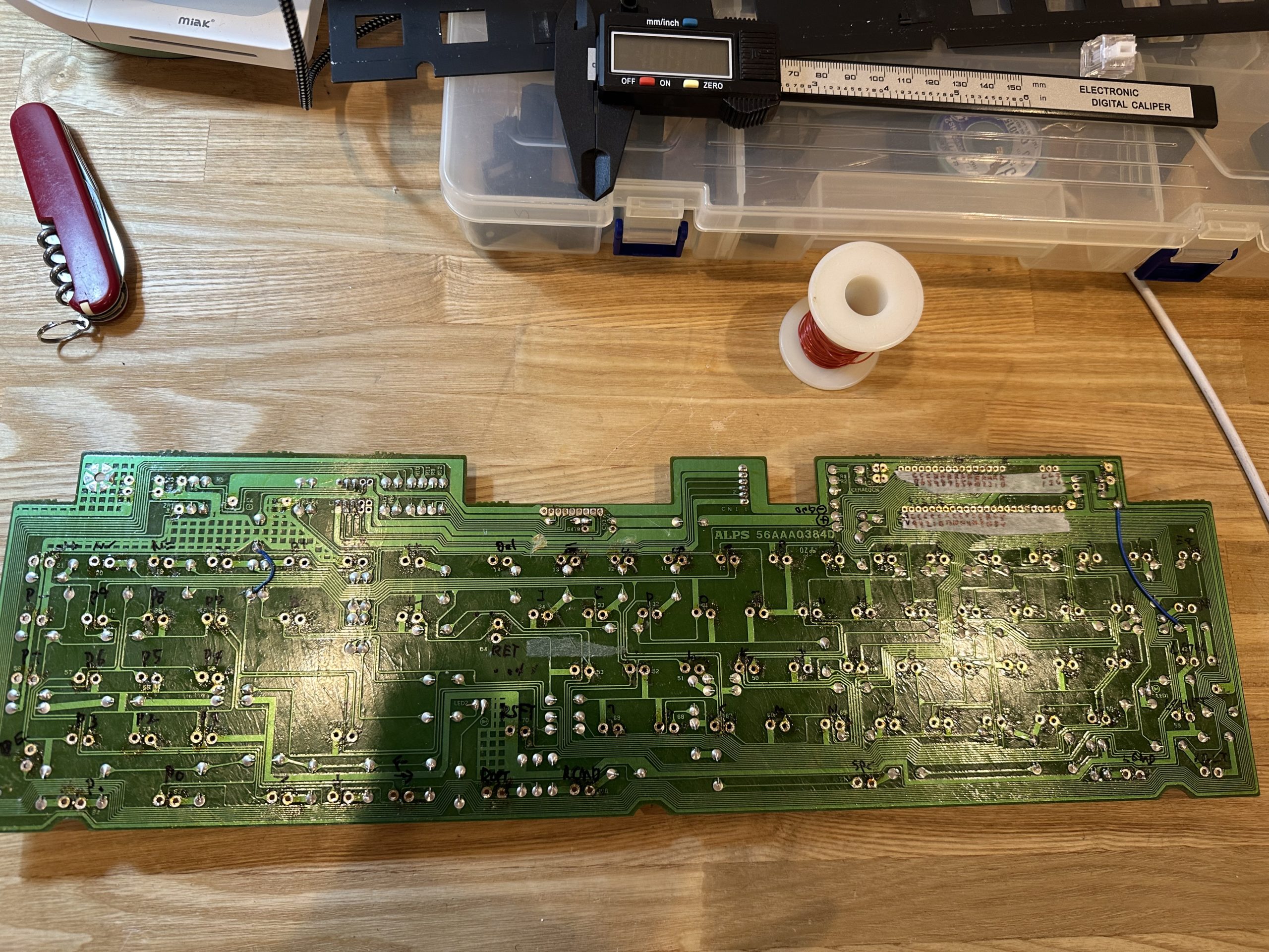
The matrix pattern of the original NeXT keyboard is analyzed. With a tester in hand, we follow the pattern on the back side.
This time, I will make the keyboard without cutting the pattern. We will also make a board on which Pi Pico will be placed, and fit it into the place where the original controller was removed.
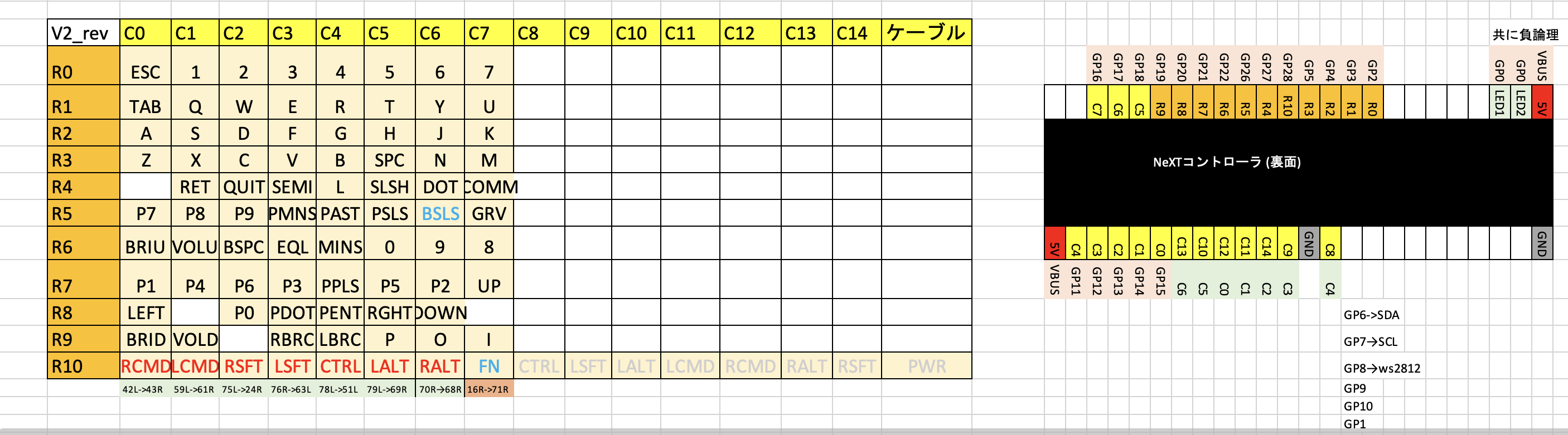
The following figure shows the result of the analysis.
The keys close to each other are compactly arranged, and the matrix looks like it could fit in an 8×10… but only the modifier keys are sticking out. What’s this? If you look closely, you can see that the line marked R10 is GND. So, these keys are not matrix keys, but direct keys.
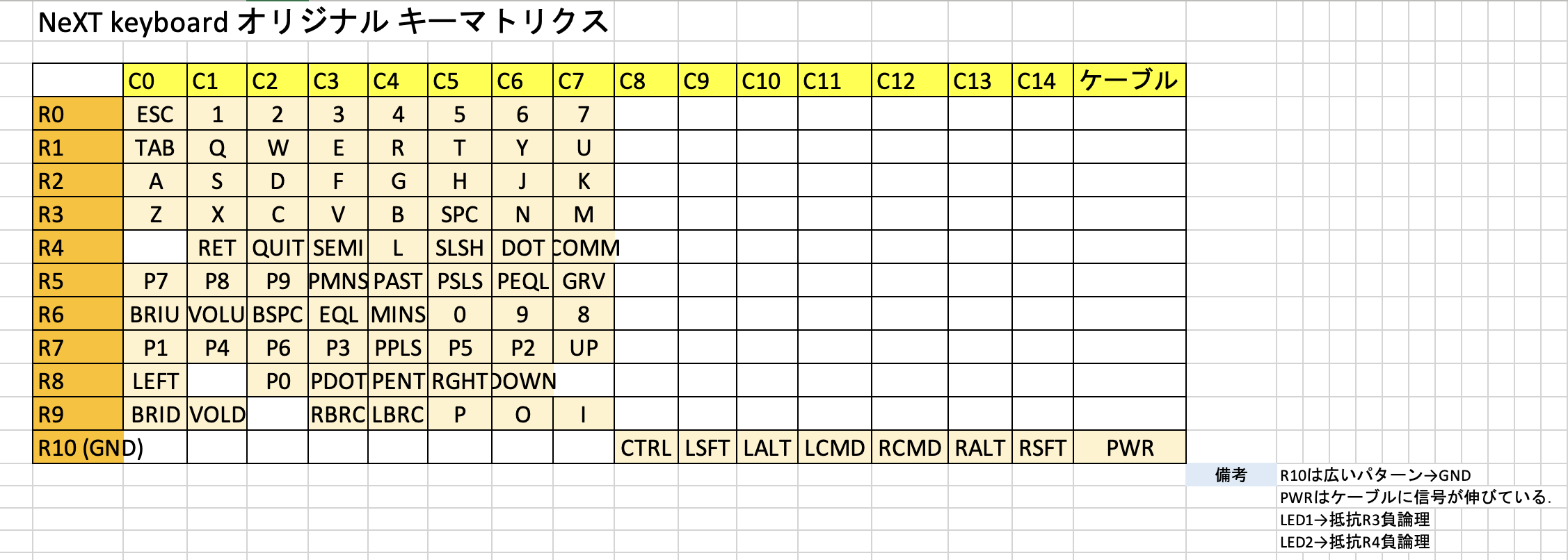
Since we are not using a microcontroller with that many pins, we integrate the modifier keys into the matrix by following the GND pattern and removing the jumper from GND to make it a single bus.
The final matrix is as follows. The modifier is integrated in the rows and columns for the convenience of the Pi Pico board.
We will make a board to convert this matrix to Pi Pico. This is very convenient because the modifier keys can be integrated only on this board.

After designing the board, I ordered it from Elecrow. The cost of the board is $1.00. Shipping is about $15 and it takes less than a week. I decided that it would be better to solve the problem with money than to try hard to arrange the line where the bug would enter.
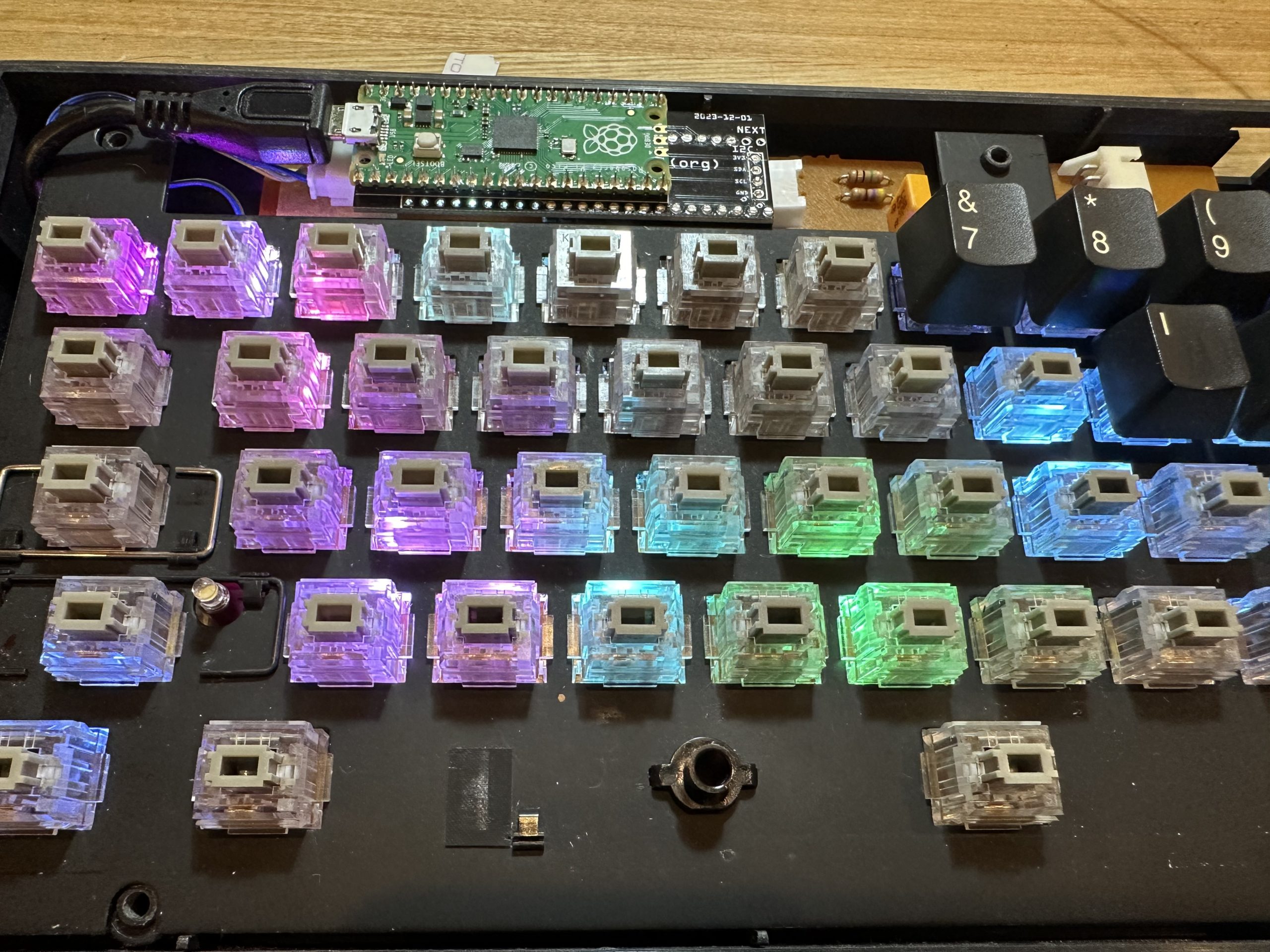
Mounting
I looked around for a way to make the LEDs glow from behind the keys, but in the end I decided to replace all the switches.
The board has a single-sided pattern, so it is easy to remove the solder.
However, the copper foil pattern itself is brittle and easily peels off since it is an old board.
With great care, we removed the solder and the switches.
Remove…
Remove…
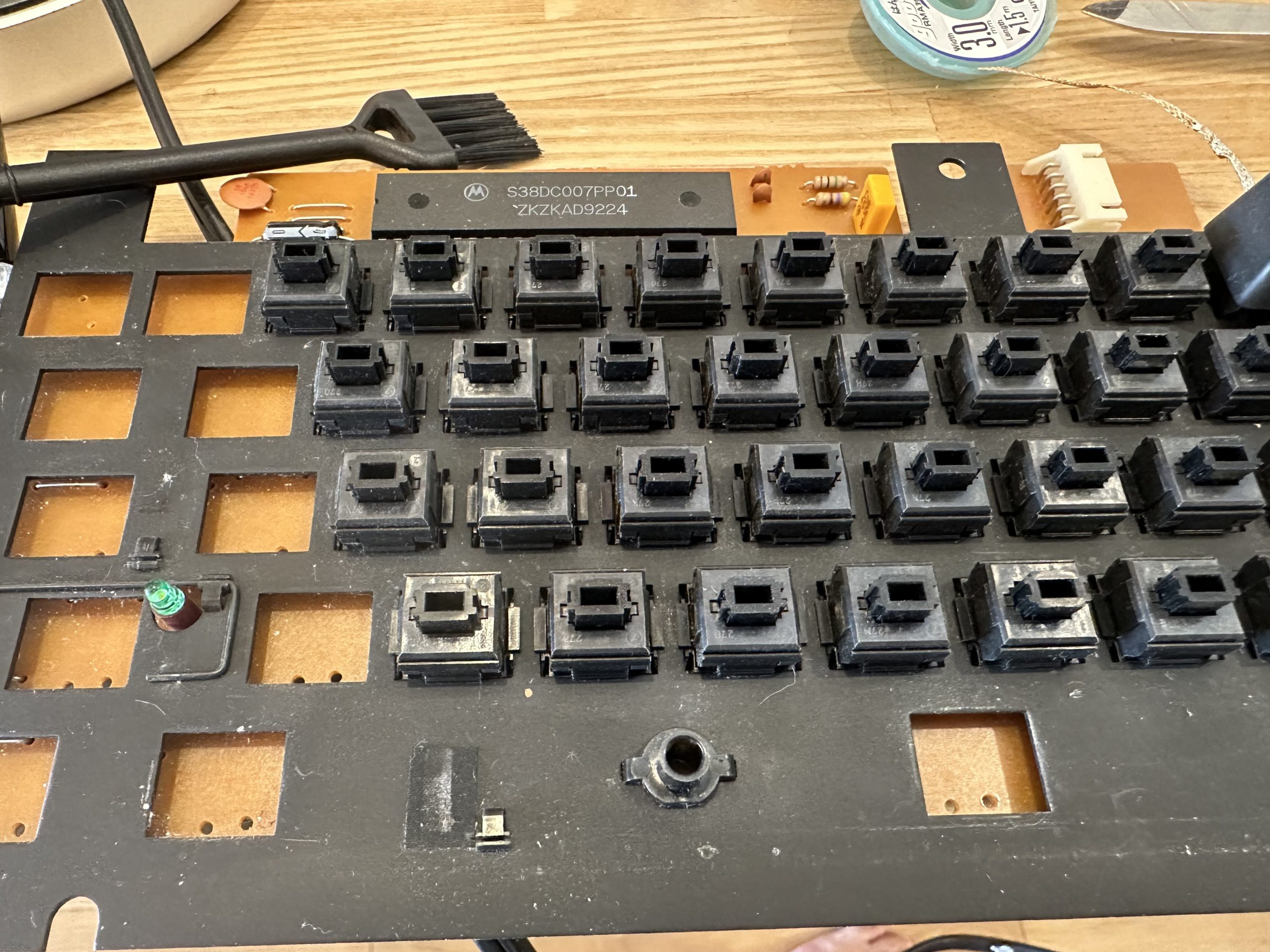
Remove…
Voila!

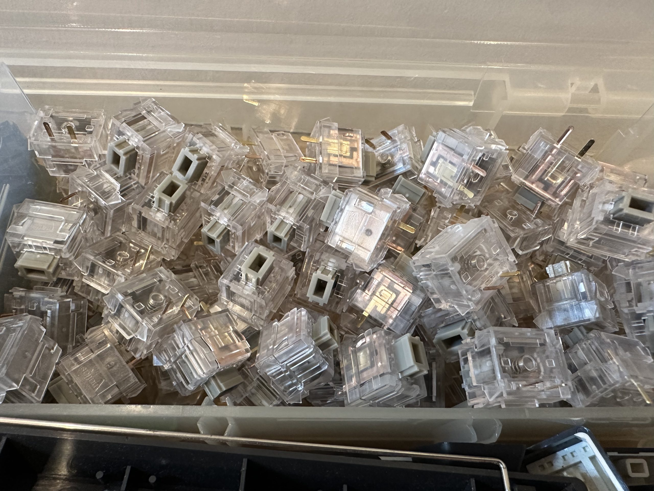
I got Matias Click Switch Gray and White from FILCO Direct. Only the numeric keypad is made to click with White.
The jumper on the surface of the switch will be removed and re-mounted on the back side of the switch, because the LED strip will be in the way.
The consumption speed of the desoldering wire is extraordinary.
In the end, I had to remove more than 90% of the mounted parts.
In addition, the Caps Lock LED is changed to a white LED.
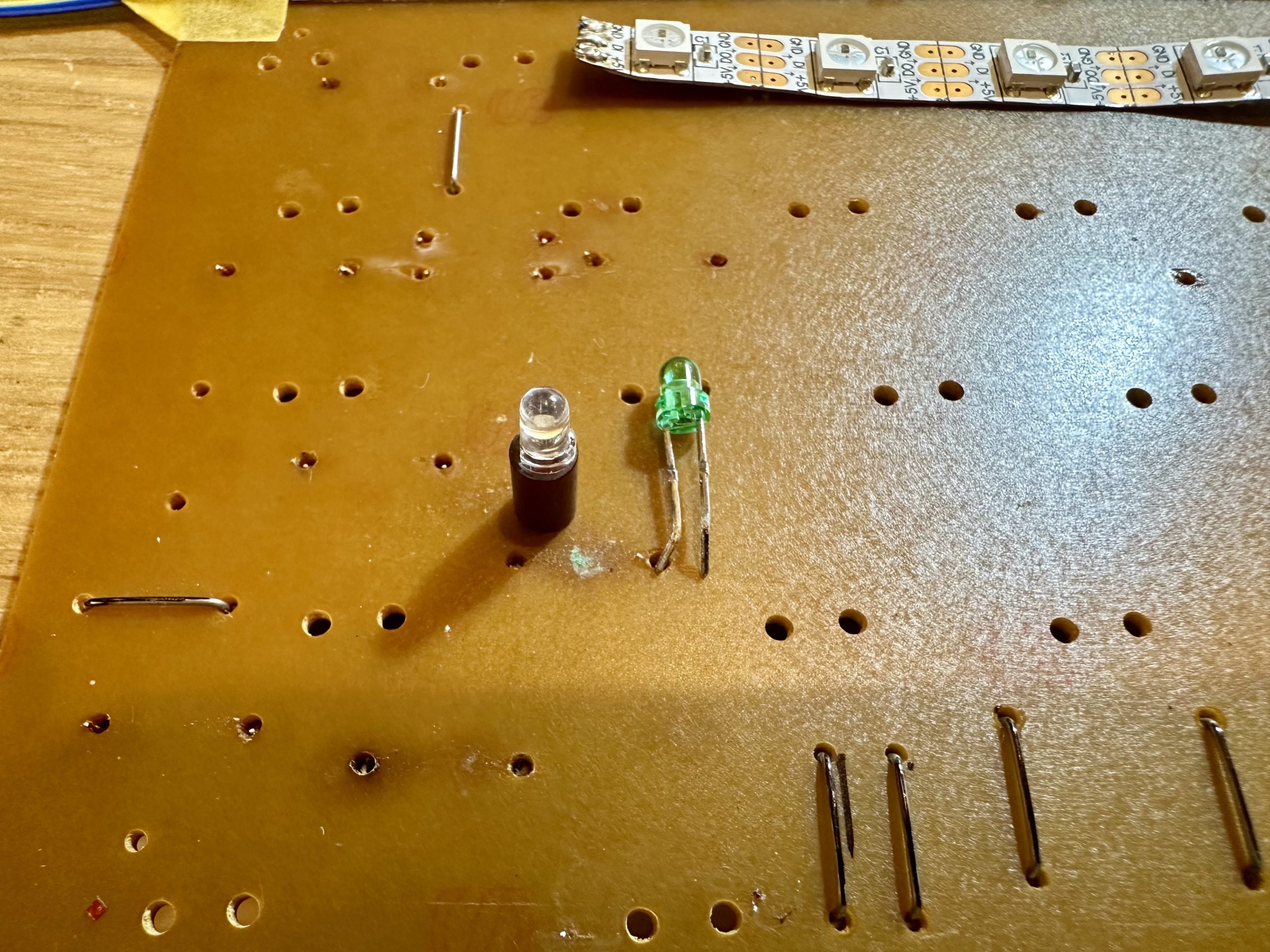
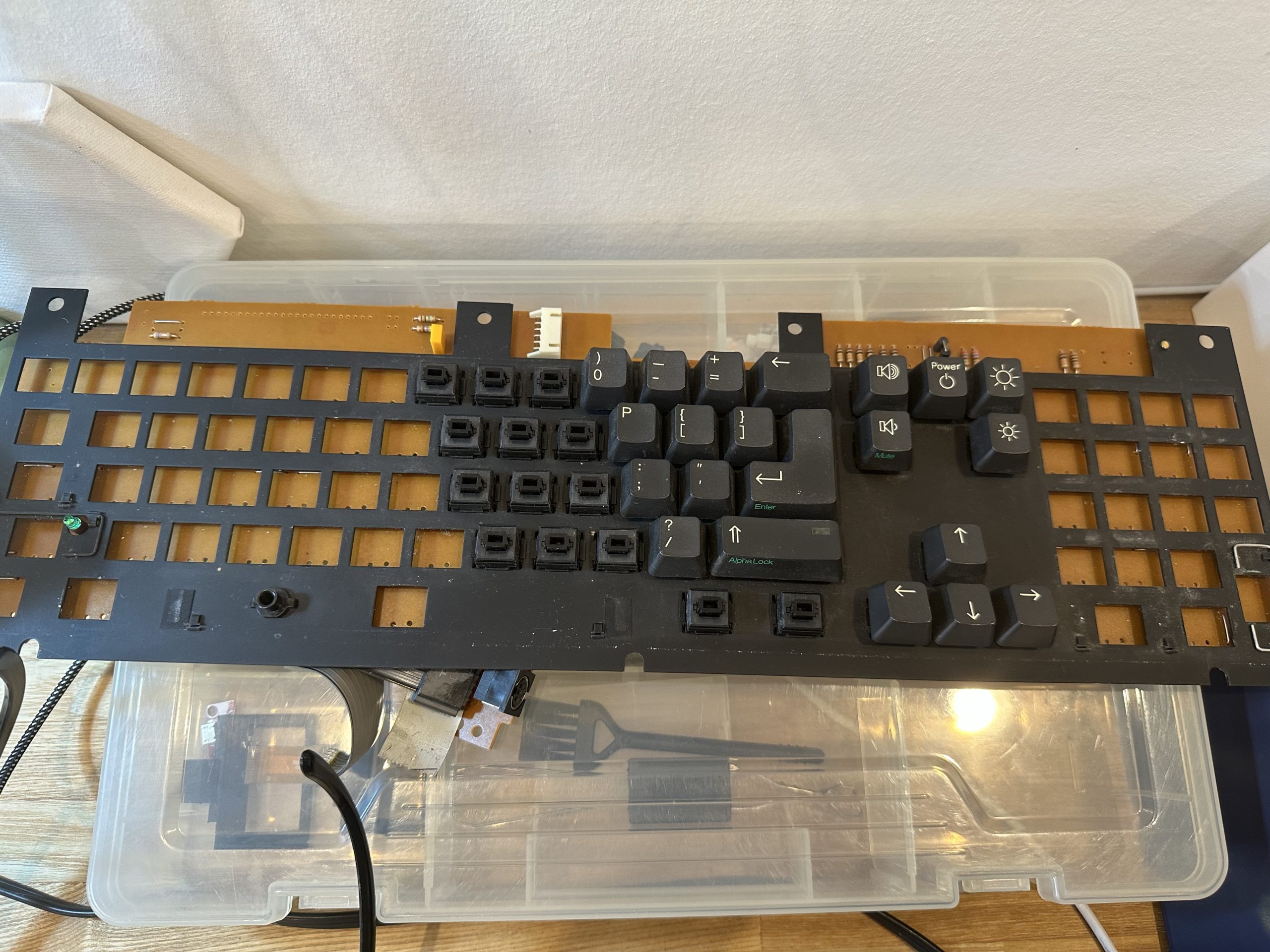
Next, I installed LED strips to make the LEDs shine. 10mm wide LED strips are commonly used, but they seem to interfere with the keyswitch (just barely), so I got 5mm wide ones this time.
First row…
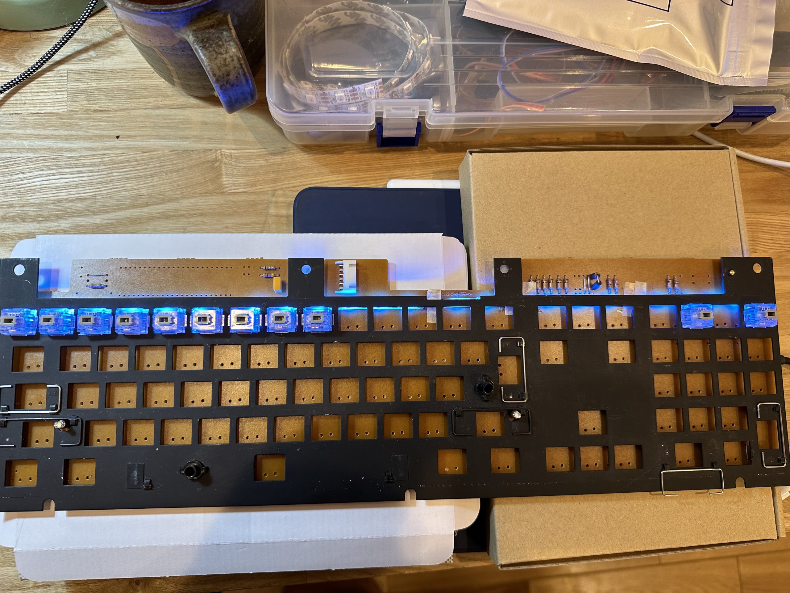
2nd row…
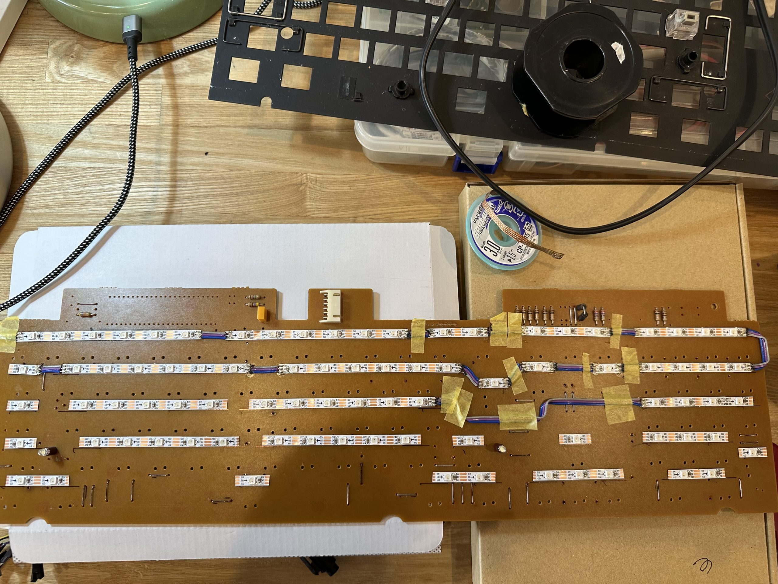
All rows…
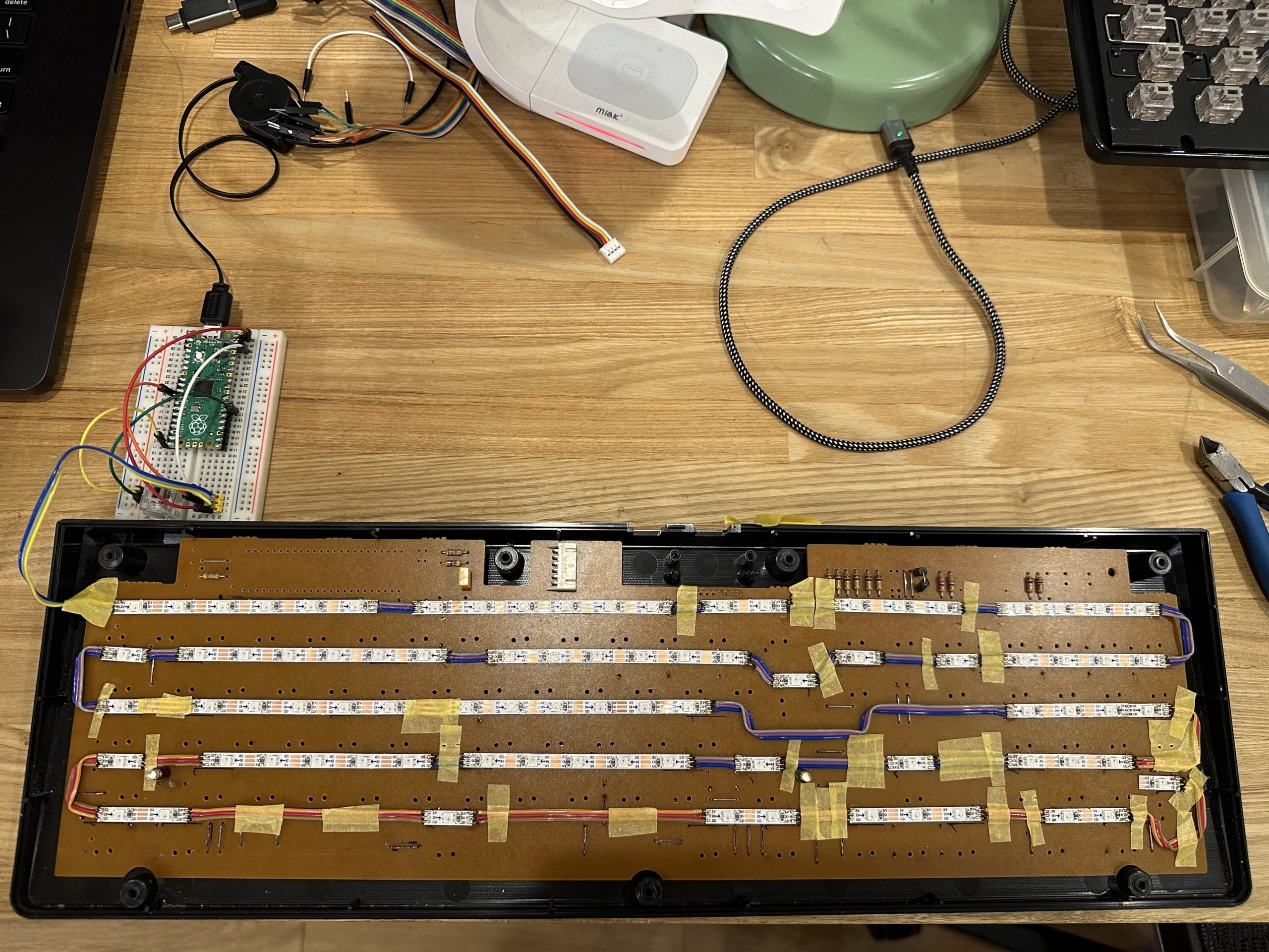
Lit!

This is the end of the work on the board, so let’s solder the keyswitch.
Once the keyswitch is soldered, the LED strip cannot be touched, so it is necessary to double-check for poor contact.
Finishing
When I finished soldering the keyswitches, the key matrix conversion board arrived from Shenzhen.
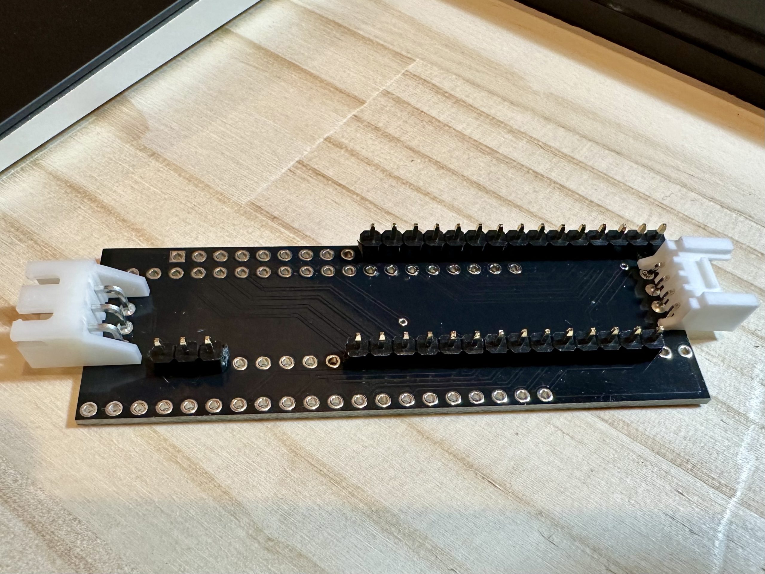
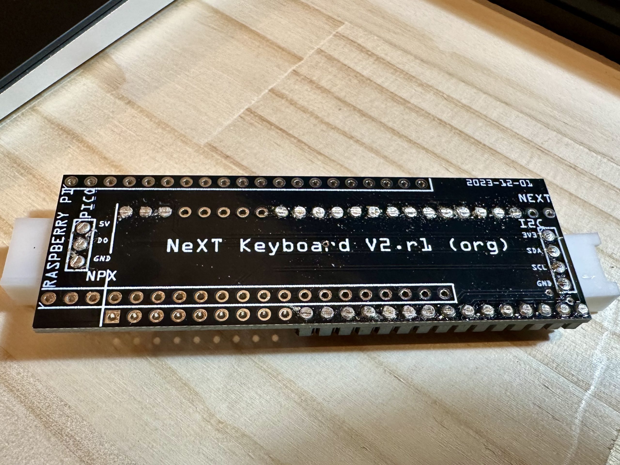
Connectors for I2C and WS2812 were also pulled out.
This is used to bridge the Raspberry Pi Pico and the keyboard board.
As long as there are no bugs on the board, the wiring work can be completed without connecting a single wire.
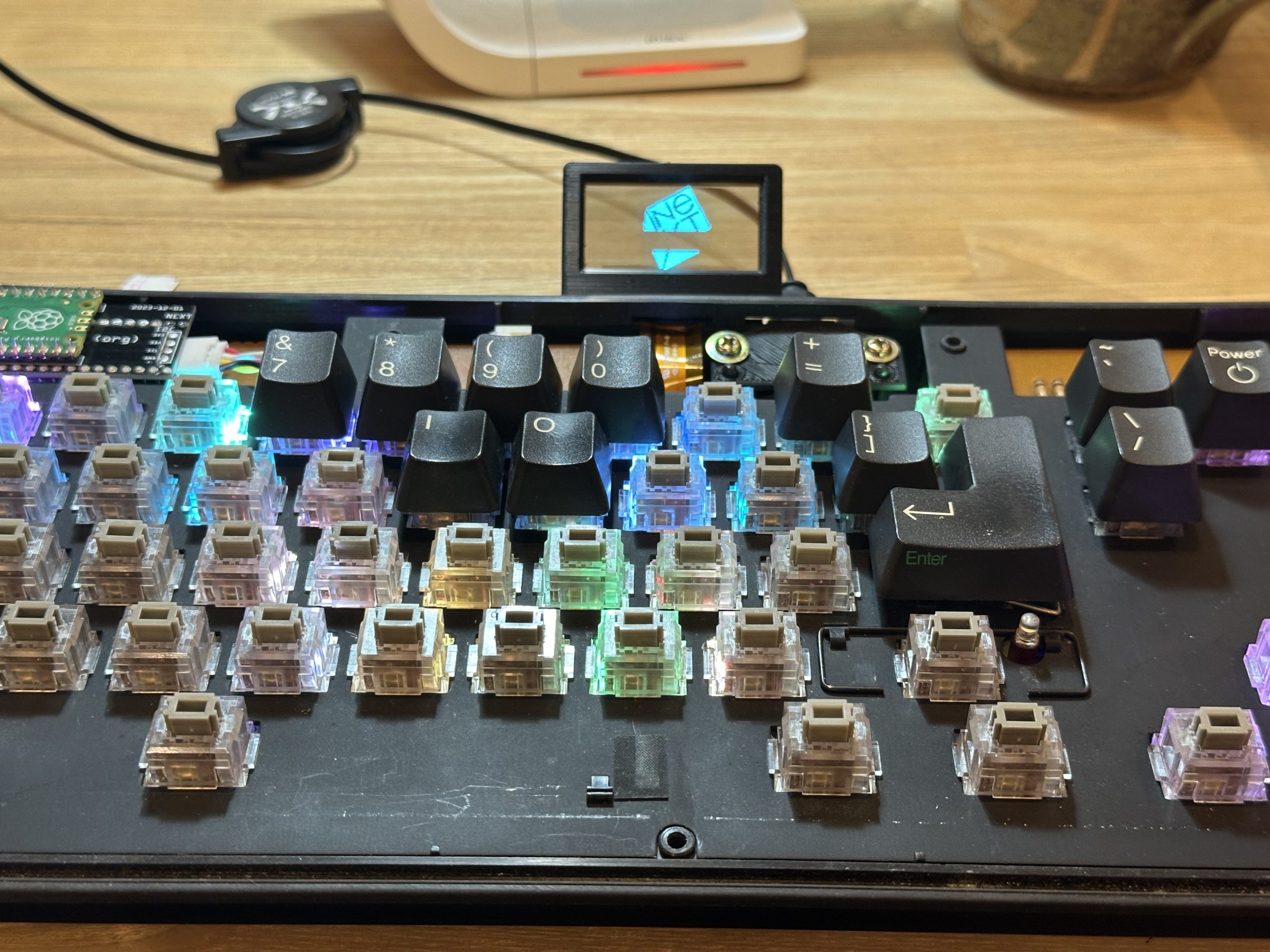
Test lighting! Good!
The transparent OLED is also attached via I2C.
This is exactly the same as V1, so it is easy to do.
All that is left is to assemble it.
Completed!
It’s done!
The code of QMK is available in GitHub.
Bugs and failures along the way
- At first, I misunderstood how to light the LEDs on the main board, and thought the 5V line was GND. I made the first conversion board as it was, so I had to do a major re-do and ended up reordering.
- After installing the LED strips and soldering all the keyswitches, I did a key matrix test and found that one line was unresponsive. The tester found that only when the LED strip was connected, 5V was connected to the line in question. This was because when the jumper wire was replaced, a small portion of the jumper wire was in contact with the 5V of the LED strip.
Conclusion
It is fun to revive old keyboards by modifying them.
In particular, keyboards with mechanical switches from the 1990s are worth reviving because they have a good feel when you hit the keys.
If you find a good keyboard in a junk shop, you can get it immediately!
Merry Christmas and a happy new year!